Trunking allows us to carry traffic for multiple VLANs across a single physical link between Cisco switches. This is achieved by encapsulating VLAN information within the Ethernet frame using protocols like 802.1Q.
In this post, we’ll explore configuring Trunk on Cisco switches using Packet Tracer to enable communication between VLANs. Before we dive in, make sure to check out this post if you want to learn about VLAN configuration. Additionally, we talk about Manual Trunking and Dynamic Trunking Protocol (DTP).
Manual Trunking vs. Dynamic Trunking Protocol (DTP)
Both manual trunking and DTP (Dynamic Trunking Protocol) allow you to configure switch ports for carrying traffic from multiple VLANs, but they achieve this in different ways:
Manual Trunking
- Offers more granular control over the trunking configuration.
- Requires explicit configuration on both switch ports involved in the trunk.
Dynamic Trunking Protocol (DTP)
- Automates trunk negotiation between Cisco devices.
- Simplifies configuration but can lead to unexpected behavior if not carefully managed.
DTP have many negation mode available:
- Desirable (default): Attempts to establish a trunk but falls back to access mode if negotiation.
- On (trunking mode): Forces the port into trunk mode, potentially causing issues if the other device doesn’t support DTP.
- Auto: Only initiates trunk negotiation, requiring the other device to also be in auto or desirable.
- Nonnegotiate: Disables DTP negotiation altogether.
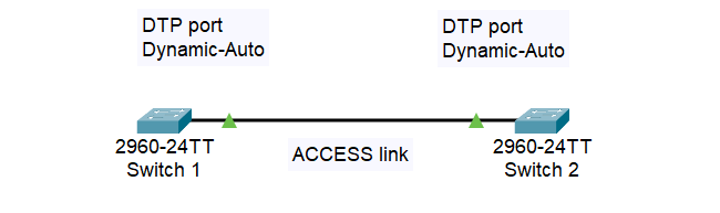
There are many cases when we use DTP. For instance, in this case, if we have a DTP port set to Dynamic-Auto on Switch 1, when connect that port to Switch 2 also set as Dynamic-Auto, DTP port, we will automatically have Access link between two switches.
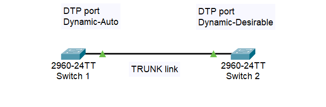
However, in this case, if we have one end of the switch (Switch 1) to be set to Dynamic-Auto and the other end (Switch 2) is set to Dynamic-Desirable, we will have an automatic Trunk link and add all VLANs to it.
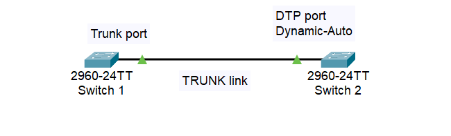
And in this case, we have a trunk port manually configured on Switch 1, and on Switch 2 is set to Dynamic-Auto, DTP, we will automatically have a Trunk link between two switches.
Below is the summary of DTP Possibilities:
| Scenario (Switch 1 / Switch 2) | Result | Security Risk |
| Trunk / Trunk (DTP on) | Trunk Link Established | High – Forced trunking, bypasses negotiation |
| Desirable / Trunk | Trunk Link Established (if both support DTP) | Moderate – Unintended trunking on desirable switch |
| Desirable / Desirable (Default) | Trunk Link Established (if both support DTP) or Fallback to Access Mode (if negotiation fails) | Low – Negotiation prevents accidental trunking |
| Desirable / Auto | Trunk Link Established (if both initiate negotiation) | Moderate – Unintended trunking on desirable switch |
| Auto / Auto | Fallback to Access Mode (unless both initiate negotiation simultaneously) | None – Requires specific timing for trunk formation |
| Nonegotiate / Any Mode | Switch with nonegotiate remains in Access Mode | None – Prevents accidental trunking |
| Desirable / Nonegotiate | Switch with nonegotiate remains in Access Mode, Desirable switch falls back to Down | Moderate (Desirable switch) – Potential configuration error or security measure |
| Auto / Nonegotiate | Switch with nonegotiate remains in Access Mode, Auto switch falls back to Down | Low (Auto switch) – Requires manual intervention |
| Auto / Trunk | Trunk Link Established (if Auto switch responds to Trunk initiation) | Moderate (depends on switch configuration) – Potential for unintended trunking |
Recommendation
DTP can be useful for quick setups in controlled environments where all devices are Cisco switches. However, you should perform manual trunking for its security and control benefits. Trunk link can give access to all VLANs in the network, so a misconfigured trunk could expose sensitive data if unauthorized access occurs.
Lab 1: Manual Trunking
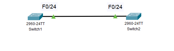
Network Topology
Here is the network topology:
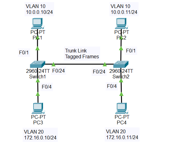
- On Switch 1, we’ll configure F0/1 on VLAN 10 and F0/4 on VLAN 20
- On Switch 2, we’ll configure F0/1 on VLAN 10 and F0/4 on VLAN 20
- VLAN 10 is named “HR” and VLAN 20 is named “Marketing“
- We configure the Trunk link on F0/24 on both switches
Create VLANs on Switch 1 and Switch 2
First, we check the running configuration on Switch 1 with the command “show running-config“. We should see port F0/1 and F0/4 currently don’t have any configuration on them.
Switch1>enable
Switch1#show running-config
Building configuration...

Current configuration : 1080 bytes
!
interface FastEthernet0/1
!
interface FastEthernet0/4
Next, we configure the VLANs
Switch1>enable
Switch1#configure terminal
Enter configuration commands, one per line.  End with CNTL/Z.
Switch1(config)#vlan 10
Switch1(config-vlan)#name HR
Switch1(config-vlan)#exit
Switch1(config)#vlan 20
Switch1(config-vlan)#name Marketing
Switch1(config-vlan)#exit
Switch1(config)#do show vlan brief

VLAN Name                             Status    Ports
---- -------------------------------- --------- -------------------------------
1    default                          active    Fa0/1, Fa0/2, Fa0/3, Fa0/4
                                                Fa0/5, Fa0/6, Fa0/7, Fa0/8
                                                Fa0/9, Fa0/10, Fa0/11, Fa0/12
                                                Fa0/13, Fa0/14, Fa0/15, Fa0/16
                                                Fa0/17, Fa0/18, Fa0/19, Fa0/20
                                                Fa0/21, Fa0/22, Fa0/23, Fa0/24
                                                Gig0/1, Gig0/2
10   HR                               active
20   Marketing                        active
After that, assign ports to VLAN 10 and VLAN 20
Switch1>enable
Switch1#configure terminal
Enter configuration commands, one per line.  End with CNTL/Z.
Switch1(config)#int f0/1
Switch1(config-if)#switchport mode access
Switch1(config-if)#switchport access vlan 10
Switch1(config-if)#exit
Switch1(config)#int f0/4
Switch1(config-if)#switchport mode access
Switch1(config-if)#switchport access vlan 20
Switch1(config-if)#do show vlan brief

VLAN Name                             Status    Ports
---- -------------------------------- --------- -------------------------------
1    default                          active    Fa0/2, Fa0/3, Fa0/5, Fa0/6
                                                Fa0/7, Fa0/8, Fa0/9, Fa0/10
                                                Fa0/11, Fa0/12, Fa0/13, Fa0/14
                                                Fa0/15, Fa0/16, Fa0/17, Fa0/18
                                                Fa0/19, Fa0/20, Fa0/21, Fa0/22
                                                Fa0/23, Fa0/24, Gig0/1, Gig0/2
10   HR                               active    Fa0/1
20   Marketing                        active    Fa0/4
We have finished creating VLANs on Switch 1, you should repeat the same steps above for Switch 2. When you done, move on to the next section.
Enabling Trunking
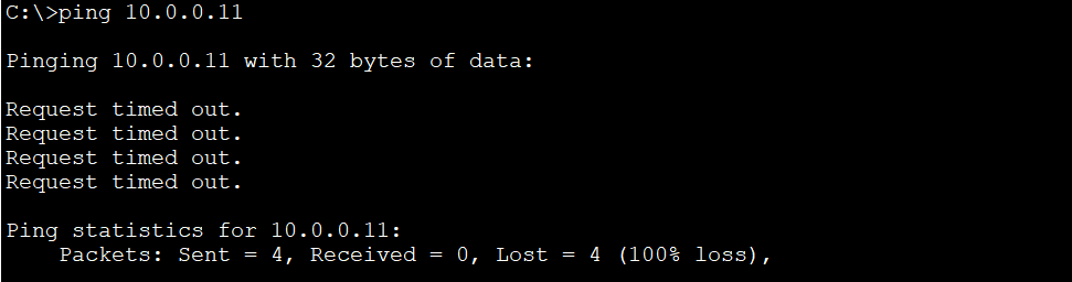
For testing purpose, before configuring the trunk link, we won’t be able to ping PC2 (10.0.0.11, VLAN 10) on Switch 2 from PC1 (10.0.0.10, VLAN 10) on Switch 1.
Now let’s build the trunk link. We will configure port F0/24. In this case, we choose Switch 1 to configure the trunk link:
Switch1#enable
Switch1#configure terminal
Enter configuration commands, one per line.  End with CNTL/Z.
Switch1(config)#int f0/24
Switch1(config-if)#switchport mode trunk

Switch1(config-if)#
%LINEPROTO-5-UPDOWN: Line protocol on Interface FastEthernet0/24, changed state to down

%LINEPROTO-5-UPDOWN: Line protocol on Interface FastEthernet0/24, changed state to up

Switch1(config-if)#switchport trunk allow vlan 10,20
Switch1(config-if)#exit
- Enter interface configuration mode: “int f0/24“
- Set interface mode to trunk: “switchport mode trunk“
- Allow specific VLANs on the trunk: “switchport trunk allow vlan 10,20“
As you can see, after configuring F0/24 as a trunk port and allowing VLANs 10 and 20 on the trunk, the interface goes through a state change (“up” and “down“) due to the configuration changes being applied. This is indicated by the %LINEPROTO-5-UPDOWN message.
Verify Trunking
To look at the status of that trunk link, we use the command “show interfaces trunk“. The output shows that interface Fa0/24 is configured as a trunk port, allowing VLANs 10 and 20 to traverse the trunk. It also indicates that both VLANs are currently active and forwarding traffic. The Mode is “on” indicates that the interface is in trunking mode.
Switch1#show interfaces trunk
Port        Mode         Encapsulation  Status        Native vlan
Fa0/24      on           802.1q         trunking      1

Port        Vlans allowed on trunk
Fa0/24      10,20

Port        Vlans allowed and active in management domain
Fa0/24      10,20

Port        Vlans in spanning tree forwarding state and not pruned
Fa0/24      10,20
If you use command “show running-config“, you will see the configuration for port F0/24 also
Switch1#show  running-config
Building configuration...

Current configuration : 1242 bytes
!
interface FastEthernet0/24
 switchport trunk allowed vlan 10,20
 switchport mode trunk
We have finished configuring trunk port on Switch 1. Now let’s take a look at Switch 2 trunk status
Switch2>enable
Switch2#show interfaces trunk
Port        Mode         Encapsulation  Status        Native vlan
Fa0/24      auto         n-802.1q       trunking      1

Port        Vlans allowed on trunk
Fa0/24      1-1005

Port        Vlans allowed and active in management domain
Fa0/24      1,10,20

Port        Vlans in spanning tree forwarding state and not pruned
Fa0/24      1,10,20
You will notice that the Dynamic Trunking Protocol (DTP) automatically figure out F0/24 is a trunk port with the Mode is “auto“, meaning the switch will negotiate the trunking mode with its neighboring device. Also, VLANs 1 through 1005 are allowed on the trunk port. This is the default behavior when using the “auto” mode for trunk negotiation.
Next, use command “show running-config” to see the configuration for port F0/24 on Switch 2
Switch2#show running-config
Building configuration...

Current configuration : 1183 bytes
!
interface FastEthernet0/24
You will see that although the trunk link is configured automatically, the configuration for port F0/24 on Switch 2 is blank. Dynamic Trunking Protocol (DTP) is used to negotiate trunking with the neighboring device.
Let’s manually configure interface F0/24 as trunk port on Switch 2. This is a preferable method since we have full control over its configuration.
Switch2#configure terminal
Enter configuration commands, one per line.  End with CNTL/Z.
Switch2(config)#int f0/24
Switch2(config-if)#switchport mode trunk
Switch2(config-if)#switchport trunk allow vlan 10,20
Switch2(config-if)#do show interfaces trunk
Port        Mode         Encapsulation  Status        Native vlan
Fa0/24      on           802.1q         trunking      1

Port        Vlans allowed on trunk
Fa0/24      10,20

Port        Vlans allowed and active in management domain
Fa0/24      10,20

Port        Vlans in spanning tree forwarding state and not pruned
Fa0/24      20
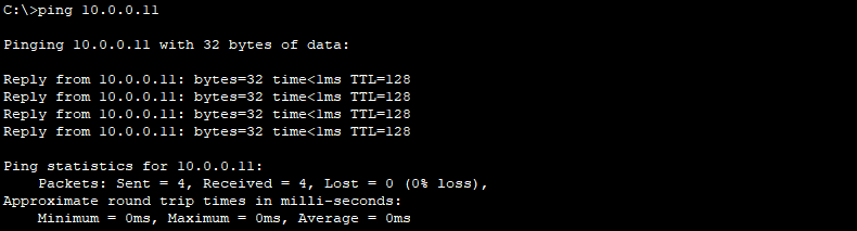
Now you can see only VLAN 10 and 20 is allowed on the trunk link on Switch 2. Next, let’s test to see if we can ping PC2 (10.0.0.11, VLAN 10) on Switch 2 from PC1 (10.0.0.10, VLAN 10) on Switch 1. The ping should be successful:
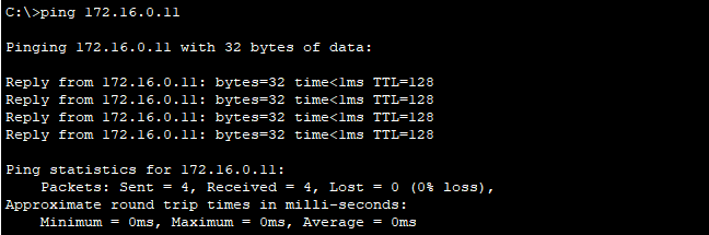
The ping will also be successful if we ping PC4 (172.16.0.11, VLAN 20) on Switch 2 from PC3 (172.16.0.10, VLAN 20) on Switch 1.
Lab 2: Dynamic Trunking Protocol (DTP)
Network Topology
Let’s examine the DTP behavior with this lab 2. We will configure some switches and go through some possibilities.
- F0/24 on Switch 2 will have no configuration on it, meaning that F0/24 is DTP port by default
- We modify Switch 1 to go through different possibilities
On Switch 2, use commands “show int trunk” and “show interface f0/24 switchport“, we should see no trunk port configure yet.
Switch2>enable
Switch2#show int trunk


Switch2#show interface f0/24 switchport
Name: Fa0/24
Switchport: Enabled
Administrative Mode: dynamic auto
Operational Mode: static access
Administrative Trunking Encapsulation: dot1q
Operational Trunking Encapsulation: native
Negotiation of Trunking: On
Access Mode VLAN: 1 (default)
Trunking Native Mode VLAN: 1 (default)
From the output, we see that F0/24 is under VLAN 1, meaning that F0/24 is an access port. If you use “show vlan brief“, you can see F0/24 belong to VLAN 1 either.
Switch2#show vlan brief

VLAN Name                             Status    Ports
---- -------------------------------- --------- -------------------------------
1    default                          active    Fa0/1, Fa0/2, Fa0/3, Fa0/4
                                                Fa0/5, Fa0/6, Fa0/7, Fa0/8
                                                Fa0/9, Fa0/10, Fa0/11, Fa0/12
                                                Fa0/13, Fa0/14, Fa0/15, Fa0/16
                                                Fa0/17, Fa0/18, Fa0/19, Fa0/20
                                                Fa0/21, Fa0/22, Fa0/23, Fa0/24
                                                Gig0/1, Gig0/2
Do the same commands on Switch 1, you will notice that F0/24 is also an access port, no configuration on it.
Switch1>enable
Switch1#show int trunk


Switch1#show interface f0/24 switchport
Name: Fa0/24
Switchport: Enabled
Administrative Mode: dynamic auto
Operational Mode: static access
Administrative Trunking Encapsulation: dot1q
Operational Trunking Encapsulation: native
Negotiation of Trunking: On
Access Mode VLAN: 1 (default)
Trunking Native Mode VLAN: 1 (default)

Switch1#show vlan brief

VLAN Name                             Status    Ports
---- -------------------------------- --------- -------------------------------
1    default                          active    Fa0/1, Fa0/2, Fa0/3, Fa0/4
                                                Fa0/5, Fa0/6, Fa0/7, Fa0/8
                                                Fa0/9, Fa0/10, Fa0/11, Fa0/12
                                                Fa0/13, Fa0/14, Fa0/15, Fa0/16
                                                Fa0/17, Fa0/18, Fa0/19, Fa0/20
                                                Fa0/21, Fa0/22, Fa0/23, Fa0/24
                                                Gig0/1, Gig0/2
So, we can see that both ends at the moment are configured as DTP Dynamic-Auto, it means we have an access link between the two switches. In other words, we are connected with VLAN 1 between Switch 1 and Switch 2.
Change from Dynamic-Auto to Dynamic-Desirable on Switch 1
On Switch 1, to change the port to be Dynamic-Desirable, the command is “switchport mode dynamic desirable“:
Switch1>enable
Switch1#configure terminal
Enter configuration commands, one per line.  End with CNTL/Z.
Switch1(config)#int f0/24
Switch1(config-if)#switchport mode dynamic desirable

Switch1(config-if)#
%LINEPROTO-5-UPDOWN: Line protocol on Interface FastEthernet0/24, changed state to up

%LINEPROTO-5-UPDOWN: Line protocol on Interface FastEthernet0/24, changed state to down

%LINEPROTO-5-UPDOWN: Line protocol on Interface FastEthernet0/24, changed state to up

Switch1(config-if)#exit
Now, we take a look at the port status of Switch 1. Notice that port F0/24 has a trunking status configured automatically:
Switch1#show int trunk
Port        Mode         Encapsulation  Status        Native vlan
Fa0/24      desirable    n-802.1q       trunking      1

Port        Vlans allowed on trunk
Fa0/24      1-1005

Port        Vlans allowed and active in management domain
Fa0/24      1

Port        Vlans in spanning tree forwarding state and not pruned
Fa0/24      1
You should see the same result in the Switch 2, with F0/24 operate as trunk port:
Switch2#show int trunk
Port        Mode         Encapsulation  Status        Native vlan
Fa0/24      auto         n-802.1q       trunking      1

Port        Vlans allowed on trunk
Fa0/24      1-1005

Port        Vlans allowed and active in management domain
Fa0/24      1

Port        Vlans in spanning tree forwarding state and not pruned
Fa0/24      1
Turning off DTP
In reality, you should restrict VLAN 1 from traversing the trunk because of security risk. Trunk ports give an end user a lot of access to the network. Also, we don’t want our ports to be automatically configured for trunk ports without any administration.
Let’s turn off DTP on Switch 2:
Switch2#configure terminal
Enter configuration commands, one per line.  End with CNTL/Z.
Switch2(config)#int range f0/1 - 24 , g0/1 - 2
Switch2(config-if-range)#switchport mode access
Switch2(config-if-range)#%SPANTREE-2-RECV_PVID_ERR: Received 802.1Q BPDU on non trunk FastEthernet0/24 VLAN1.

%SPANTREE-2-BLOCK_PVID_LOCAL: Blocking FastEthernet0/24 on VLAN0001. Inconsistent port type.


Switch2(config-if-range)#switchport nonegotiate
Switch2(config-if-range)#exit
Next, we check the port status of Switch 2, notice that negotiation of Trunking is Off , and there is no trunk port configured under output of command “show int trunk“:
Switch2#show int trunk


Switch2#show interface f0/24 switchport
Name: Fa0/24
Switchport: Enabled
Administrative Mode: static access
Operational Mode: static access
Administrative Trunking Encapsulation: dot1q
Operational Trunking Encapsulation: native
Negotiation of Trunking: Off
Access Mode VLAN: 1 (default)
Trunking Native Mode VLAN: 1 (default)
Conclusion
To sum up, while DTP offers convenience for quick setups, understanding its limitations and potential security risks is crucial. For secure and controlled multi-VLAN communication, manual trunking is the recommended approach.