This lab will guide you through step by step of configuring VLANs on a simulated network using Cisco Packet Tracer. Before we jump into the lab, let’s have a quick review of what VLAN is.
What is a VLAN?
VLAN stand for Virtual Local Area Network. VLANs allow us to segment a network, separating devices into different broadcast domains (or different subnets), even if they are physically connected to the same network switch. Devices within a VLAN can communicate freely, but traffic is restricted between VLANs, improving network security and performance.
Benefits of VLAN
- Enhanced Security: By isolating traffic, VLANs prevent unauthorized access to sensitive data across different departments or user groups.
- Improved Network Performance: Limiting broadcast traffic within a VLAN reduces congestion and improves overall network speed for devices.
- Simplified Network Management: VLANs make it easier to manage and troubleshoot network issues by segmenting devices based on their purpose.
- Increased Scalability: As your network grows, you can easily add new devices to specific VLANs without major reconfiguration.
Essential VLAN terminologies
- Broadcast Domain: A group of devices that can see all broadcast traffic on the network segment. VLANs create separate broadcast domains.
- Port: The physical connection point on a switch where devices are plugged in.
- Access Port: A switch port configured to belong to a single VLAN, restricting devices connected to that port to communicate only with others within the same VLAN.
- Trunk Port: A switch port configured to carry traffic for multiple VLANs, allowing communication between different VLANs (usually connects switches).
- VLAN ID: A unique identifier assigned to each VLAN to differentiate traffic and manage access control.
- Port tagging: or VLAN tagging, is a technique used to identify and manage different virtual LANs (VLANs) on a network switch.
Lab Setup
Here is the network topology for this lab:
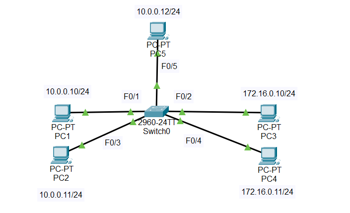
- We will configure PC1 and PC2 in VLAN 10. And PC3 and PC4 in VLAN 20.
- VLAN 10 will be named “HR”.
- VLAN 20 will be named “Marketing”.
VLAN Configuration
VLAN 1 is the default VLAN on Cisco. Therefore, all the switch port are member of VLAN1. We can check by using the command “show vlan” or “show vlan brief”.
Switch>enable
Switch#show vlan

VLAN Name                             Status    Ports
---- -------------------------------- --------- -------------------------------
1    default                          active    Fa0/1, Fa0/2, Fa0/3, Fa0/4
                                                Fa0/5, Fa0/6, Fa0/7, Fa0/8
                                                Fa0/9, Fa0/10, Fa0/11, Fa0/12
                                                Fa0/13, Fa0/14, Fa0/15, Fa0/16
                                                Fa0/17, Fa0/18, Fa0/19, Fa0/20
                                                Fa0/21, Fa0/22, Fa0/23, Fa0/24
                                                Gig0/1, Gig0/2
1002 fddi-default                     active
1003 token-ring-default               active
1004 fddinet-default                  active
1005 trnet-default                    active

VLAN Type  SAID       MTU   Parent RingNo BridgeNo Stp  BrdgMode Trans1 Trans2
---- ----- ---------- ----- ------ ------ -------- ---- -------- ------ ------
1    enet  100001     1500  -      -      -        -    -        0      0
1002 fddi  101002     1500  -      -      -        -    -        0      0
1003 tr    101003     1500  -      -      -        -    -        0      0
1004 fdnet 101004     1500  -      -      -        ieee -        0      0
1005 trnet 101005     1500  -      -      -        ibm  -        0      0
- In the output, under “VLAN Name,” you can see VLAN 1 listed as “default,”.
- The “Ports” column shows which ports are members of each VLAN. In this case, all FastEthernet (Fa0/1 – Fa0/24) and GigabitEthernet (Gig0/1, Gig0/2) ports are members of VLAN1.
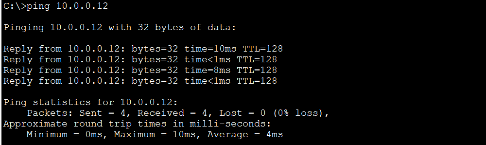
Note that because all ports are in the same VLAN 1, we are able to ping between hosts. For example, we can ping PC5 (10.0.0.12) from PC2 (10.0.0.11)
Create and name the VLAN
In this step, we will create two VLANs on the switch, that is VLAN 10 with the name “HR” and VLAN 20 with the name “Marketing”.
First, create VLAN 10 and name it “HR”:
Switch>enable
Switch#configure terminal
Enter configuration commands, one per line.  End with CNTL/Z.
Switch(config)#vlan 10
Switch(config-vlan)#name HR
Switch(config-vlan)#exit
Second, create VLAN 20 and name it “Marketing”
Switch#configure terminal
Enter configuration commands, one per line.  End with CNTL/Z.
Switch(config)#vlan 20
Switch(config-vlan)#name Marketing
Switch(config-vlan)#exit
Next, we use the command “show vlan brief” to check the result. You will notice that VLAN 10 is named “HR,” and VLAN 20 is named “Marketing.”
Switch#show vlan brief

VLAN Name                             Status    Ports
---- -------------------------------- --------- -------------------------------
1    default                          active    Fa0/1, Fa0/2, Fa0/3, Fa0/4
                                                Fa0/5, Fa0/6, Fa0/7, Fa0/8
                                                Fa0/9, Fa0/10, Fa0/11, Fa0/12
                                                Fa0/13, Fa0/14, Fa0/15, Fa0/16
                                                Fa0/17, Fa0/18, Fa0/19, Fa0/20
                                                Fa0/21, Fa0/22, Fa0/23, Fa0/24
                                                Gig0/1, Gig0/2
10   HR                               active
20   Marketing                        active
1002 fddi-default                     active
1003 token-ring-default               active
1004 fddinet-default                  active
1005 trnet-default                    active
Assign switch ports to VLAN
Next we will assign port to VLAN. Because these port belong to a single VLAN so we configure these port as access port. We will assign F0/1 and F0/3 to VLAN 10.
Switch>enable
Switch#configure terminal
Enter configuration commands, one per line.  End with CNTL/Z.
Switch(config)#int f0/1
Switch(config-if)#switchport mode access
Switch(config-if)#switchport access vlan 10
Switch(config-if)#do show vlan

VLAN Name                             Status    Ports
---- -------------------------------- --------- -------------------------------
1    default                          active    Fa0/2, Fa0/3, Fa0/4, Fa0/5
                                                Fa0/6, Fa0/7, Fa0/8, Fa0/9
                                                Fa0/10, Fa0/11, Fa0/12, Fa0/13
                                                Fa0/14, Fa0/15, Fa0/16, Fa0/17
                                                Fa0/18, Fa0/19, Fa0/20, Fa0/21
                                                Fa0/22, Fa0/23, Fa0/24, Gig0/1
                                                Gig0/2
10   HR                               active    Fa0/1
20   Marketing                        active
1002 fddi-default                     active
1003 token-ring-default               active
1004 fddinet-default                  active
1005 trnet-default                    active
Switch>enable
Switch#configure terminal
Enter configuration commands, one per line.  End with CNTL/Z.
Switch(config)#int f0/3
Switch(config-if)#switchport mode access
Switch(config-if)#switchport access vlan 10
Switch(config-if)#do show vlan

VLAN Name                             Status    Ports
---- -------------------------------- --------- -------------------------------
1    default                          active    Fa0/2, Fa0/4, Fa0/5, Fa0/6
                                                Fa0/7, Fa0/8, Fa0/9, Fa0/10
                                                Fa0/11, Fa0/12, Fa0/13, Fa0/14
                                                Fa0/15, Fa0/16, Fa0/17, Fa0/18
                                                Fa0/19, Fa0/20, Fa0/21, Fa0/22
                                                Fa0/23, Fa0/24, Gig0/1, Gig0/2
10   HR                               active    Fa0/1, Fa0/3
20   Marketing                        active
1002 fddi-default                     active
1003 token-ring-default               active
1004 fddinet-default                  active
1005 trnet-default                    active
From the output, you can see that VLAN 10 (“HR”) has ports Fa0/1 and Fa0/3 assigned to it.
Next, we continue assign port F0/2 and F0/4 to VLAN 20.
Switch>enable
Switch#configure terminal
Enter configuration commands, one per line.  End with CNTL/Z.
Switch(config)#int f0/2
Switch(config-if)#switchport mode access
Switch(config-if)#switchport access vlan 20
Switch(config-if)#exit
Switch(config)#int f0/4
Switch(config-if)#switchport mode access
Switch(config-if)#switchport access vlan 20
Switch(config-if)#do show vlan

VLAN Name                             Status    Ports
---- -------------------------------- --------- -------------------------------
1    default                          active    Fa0/5, Fa0/6, Fa0/7, Fa0/8
                                                Fa0/9, Fa0/10, Fa0/11, Fa0/12
                                                Fa0/13, Fa0/14, Fa0/15, Fa0/16
                                                Fa0/17, Fa0/18, Fa0/19, Fa0/20
                                                Fa0/21, Fa0/22, Fa0/23, Fa0/24
                                                Gig0/1, Gig0/2
10   HR                               active    Fa0/1, Fa0/3
20   Marketing                        active    Fa0/2, Fa0/4
1002 fddi-default                     active
1003 token-ring-default               active
1004 fddinet-default                  active
1005 trnet-default                    active
As you can see, the output from command “do show vlan” shows VLAN 20 (“Marketing”) has ports Fa0/2 and Fa0/4 assigned to it.
Testing the result
Now you have finished VLAN configuration, let’s try to test the connectivity between VLANs.
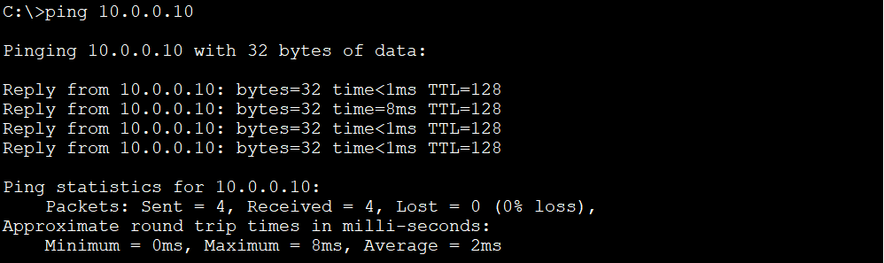
Ping PC1 (10.0.0.10, VLAN 10) from PC2 (10.0.0.11, VLAN 10). The ping should be successful because PC1 and PC2 are in the same VLAN 10.
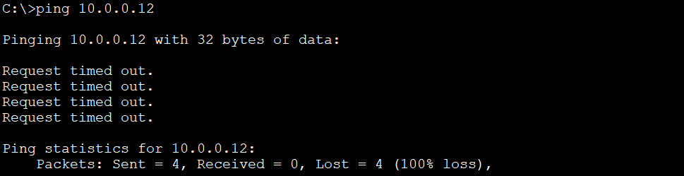
Ping PC5 (10.0.0.12, VLAN 1) from PC2 (10.0.0.11, VLAN 10). The ping will fail because PC5 and PC2 are not in the same VLAN, even though PC5 and PC2 are in the same subnet. VLAN has logically segmented the network into separate broadcast domains. To be able to communicate with each other, devices need to send their packets to a router, which then route the packets between VLANs.
Notes
- In Cisco, normal VLAN ID range is 1-1005.
- VLAN ID 1002-1005 are reserved. VLAN 1 is also reserved as the default VLAN.
- Extended Range VLANs (1006-4094): Some Cisco switches allow for an extended range of VLAN IDs, but enabling this feature might require specific configurations.
- It is not recommended to use VLAN 1 for security reason because if attackers can gain access to this VLAN, they can access all devices on the network.
If you delete a VLAN, the port assigned to that VLAN are automatically removed from the VLAN and become inactive. That port will return to the default VLAN (VLAN 1). However, if you also shutdown VLAN 1, the port will no longer be part of any VLAN. It means the port will be in an administratively down state and will not pass any traffic.
For example, let’s remove the VLAN 20 assigned to port F0/2 and F0/4 with command “no switchport access vlan“. After that, we completely remove VLAN 20 from the switch configuration with command “no vlan 20“:
Switch>enable
Switch#configure terminal
Enter configuration commands, one per line.  End with CNTL/Z.
Switch(config)#int f0/2
Switch(config-if)#no switchport access vlan 20
Switch(config-if)#exit
Switch(config)#int f0/4
Switch(config-if)#no switchport access vlan 20
Switch(config-if)#do show vlan brief

VLAN Name                             Status    Ports
---- -------------------------------- --------- -------------------------------
1    default                          active    Fa0/2, Fa0/4, Fa0/5, Fa0/6
                                                Fa0/7, Fa0/8, Fa0/9, Fa0/10
                                                Fa0/11, Fa0/12, Fa0/13, Fa0/14
                                                Fa0/15, Fa0/16, Fa0/17, Fa0/18
                                                Fa0/19, Fa0/20, Fa0/21, Fa0/22
                                                Fa0/23, Fa0/24, Gig0/1, Gig0/2
10   HR                               active    Fa0/1, Fa0/3
20   Marketing                        active
1002 fddi-default                     active
1003 token-ring-default               active
1004 fddinet-default                  active
1005 trnet-default                    active
As you can see from the output, port F0/2 and F0/4 are no longer belong to VLAN 20. Next, we remove VLAN 20:
Switch(config)#no vlan 20
Switch(config)#do show vlan brief

VLAN Name                             Status    Ports
---- -------------------------------- --------- -------------------------------
1    default                          active    Fa0/2, Fa0/4, Fa0/5, Fa0/6
                                                Fa0/7, Fa0/8, Fa0/9, Fa0/10
                                                Fa0/11, Fa0/12, Fa0/13, Fa0/14
                                                Fa0/15, Fa0/16, Fa0/17, Fa0/18
                                                Fa0/19, Fa0/20, Fa0/21, Fa0/22
                                                Fa0/23, Fa0/24, Gig0/1, Gig0/2
10   HR                               active    Fa0/1, Fa0/3
1002 fddi-default                     active
1003 token-ring-default               active
1004 fddinet-default                  active
1005 trnet-default                    active
The output shows VLAN 20 has been removed from the switch configuration. Notice that F0/2 and F0/4 are now belong to the default VLAN 1.
Here are some more commands that you may find it useful when configuring VLAN:
The “show mac address-table” command provides information about MAC addresses learned by the switch and their associated VLANs and ports:
Switch#show mac address-table
          Mac Address Table
-------------------------------------------

Vlan    Mac Address       Type        Ports
----    -----------       --------    -----

  10    000a.41b3.6e8c    DYNAMIC     Fa0/3
  10    00e0.8f33.1ac3    DYNAMIC     Fa0/1
The “show flash” command displays the contents of the flash memory on the switch, which typically stores the operating system image (IOS) and configuration files:
Switch#show flash
Directory of flash:/

    1  -rw-     4670455          <no date>  2960-lanbasek9-mz.150-2.SE4.bin
    5  -rw-        1284          <no date>  config.text
    4  -rw-         676          <no date>  vlan.dat

64016384 bytes total (59343969 bytes free)
- From the output, the third file listed is “vlan.dat“, which stores the VLAN configuration information.
The “show interfaces status” command provide a status summary of all interfaces on the switch:
Switch#show interfaces status
Port      Name               Status       Vlan       Duplex  Speed Type
Fa0/1                        connected    10         auto    auto  10/100BaseTX
Fa0/2                        connected    20         auto    auto  10/100BaseTX
Fa0/3                        connected    10         auto    auto  10/100BaseTX
Fa0/4                        connected    20         auto    auto  10/100BaseTX
You can specify a particular interface with the command “show interfaces <interface>” to view detailed information about that interface:
Switch#show interfaces F0/1
FastEthernet0/1 is up, line protocol is up (connected)
  Hardware is Lance, address is 00d0.978c.3801 (bia 00d0.978c.3801)
 BW 100000 Kbit, DLY 1000 usec,
     reliability 255/255, txload 1/255, rxload 1/255
  Encapsulation ARPA, loopback not set
...
Conclusion
You have successfully finish the basics of VLAN configuration in this Cisco Packet Tracer lab. Now you can segment your network for improved security, manageability, and performance. In the up coming post, we will learn how to configure trunk port on the switch.